- C64MIDI-INTERFACE.TXT
1993-06-29
36932
- Self-explanatory. Both ASCII and PS version.
- MK.gif
1996-11-04
29866
-
- MK7PLA.txt
1996-11-04
2341
- Schematic diagram of an Action Replay freezer cartridge clone, and the
contents of the PLA chip required for the cartridge.
- Second-SID.txt
1996-12-05
12559
- Connect a 2nd SID chip to your C64 to get stereo sounds. Written
and uploaded by Charlie Young <charlesyoung@mail.snider.net>.
- c2n-conn.jpg
2002-04-06
30421
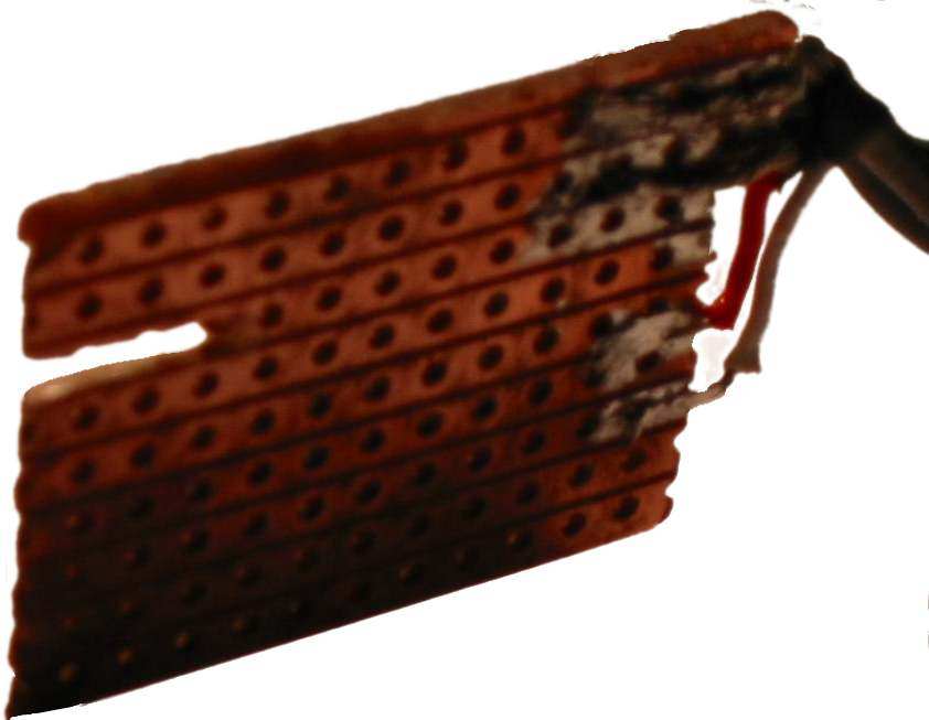
- Home-made Commodore tape drive connector. From top to bottom: GND,
VCC, tape motor (unassigned), READ (red), WRITE (white), SENSE
(unassigned).
- c2n-oric1.html
2003-11-23
2969
- Connecting a Commodore tape drive to the Oric-1. This document refers
to the figures c2n-conn.jpg and c2n-oric1.jpg.
- c2n-oric1.jpg
2002-04-06
31246
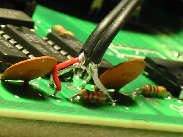
- Wiring a Commodore tape interface to the Oric-1. From left to right:
READ (red), VCC, GND, WRITE (white). The ICs on top are memory, and
the IC on the right is the sound chip.
- c64-IO-expander.zip
1998-05-19
13976
- Hardware modification to get more I/O space for the C64.
Designed and uploaded by MagerValp@Goth.Org
- c64-kernal-cartridge.gif
1997-08-18
39815
- Schematic diagram of an external KERNAL cartridge for the C64.
Drawn by Ruud Baltissen http://ruud.c64.org/.
- c64-kernal-cartridge.zip
1997-08-18
5940
- Source files of the above.
- c64-with-12volts
1996-12-14
2475
- How to make the Commodore 64 to work with a 12 volt battery.
- castest.zip
2002-08-13
368031
- Scanned images from the "Commodore" magazine article
"Testing the Commodore 64 Cassette Interface" by Don Fabrizio,
Commodore Training Manager. This article shows some Commodore 64 BASIC
code and simple connections for testing the cassette write and motor
outputs and the read and sense inputs.
- cooling-fan-C128DCR.txt
1998-01-24
10709
- Equipping the Commodore 128 DCR (metal cased 128D) with a cooling fan.
- powersupply.txt
1996-11-17
3262
- Build a heavy-duty power supply for the C64 (or VIC-20).
Note that this instruction assumes 110 V input voltage.
- reset-for-64.txt
1998-01-04
2939
- Building a RESET switch for the Commodore 64.
- rtc.gif
2001-02-22
8346
- Schematic diagram for a real time clock connected to the cassette port.
- usb-joystick.dia
2003-11-23
1318
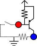
- Schematic diagram of an inverter circuit. See usb-joystick.png and
usb-joystick.html.
- usb-joystick.html
2003-11-23
9575
- Connect Atari VCS 2600 style joysticks to a USB game controller.
- usb-joystick.png
2003-11-23
4048
- Schematic diagram of an inverter circuit. The source file is
usb-joystick.dia.
- usb-joystick1.jpg
2003-11-05
10933
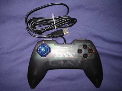
- Top view of a modified Logitech WingMan Precision USB game controller.
See usb-joystick.html.
- usb-joystick2.jpg
2003-11-05
11379
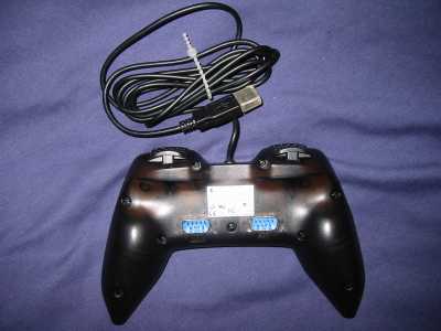
- Bottom view of a modified Logitech WingMan Precision USB game controller.
See usb-joystick.html.
- usb-joystick3.jpg
2003-11-05
15440
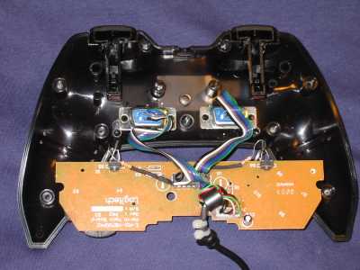
- Internal view of a modified Logitech WingMan Precision USB game controller.
See usb-joystick.html.
Mirror sites
–
General information
–
File types
–
Data transfer
The Commodore brandname and the chickenhead logo are
property of Commodore International BV, a Tulip company.