Commodore 64c rev.A and rev.B (new design). The 64c boards have the
following texts: PCB ASSY NO. 250469 and PCB NO. 252311 REV.A (or B on
newer boards). The difference between the two revisions is in the Gate
Array chip: The one in rev.B includes COLOR RAM. That is why only the
right half of the schematic diagram differs. The REV.A schematics
also has the part number 252312.
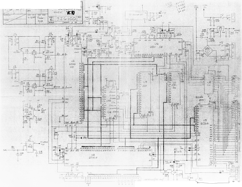
Commodore MAX Machine schematic diagram (also known as "VICKIE", VIC-10
and VC-10). The original was very noisy; the contrast was improved after
scanning. In the scanning process, the top left and bottom right corners
were omitted by mistake. The bottom right corner has been augmented.
A block diagram of the Commodore 64 internal power supply (how the
+12V, +9V and TOD clock signals are generated from the 9V AC input).
Taken from the SAMS C64 Troubleshooting Guide.
Commodore 64 Power Supply, part no. 902503-02, input 116V 60Hz 40W.
This is the North American power supply that can be taken apart.
The schematic was drawn by William Levak. According to him, the
transistor and the 300 ohm resistor can be removed and replaced with a
standard +5V 750mA voltage regulator, which is much more reliable.
Commodore 64 schematic diagram, scanned with 360 DPI, 2 colours.
This seems to be the same (buggy) schematic that was published in the
Commodore 64 Programmer's Reference Guide, but has been partially
translated into German.
The vic part contains the ROMs, SIDs, Video Controller, RAMs,
Address-decoding, Expansion Port and User Port.
The cpu part contains the Port elements (CIA), CPU, AC-Adaptor, Timer,
Port Layout
All resistors are 0.25W ±5% and all capacitors are in µF, unless otherwise
stated.
Commodore VIC-10, a.k.a. UltiMax a.k.a. "Vickie" schematic diagram, drawn
by Ruud Baltissen. For more information on this extremely rare machine,
see http://www.funet.fi/pub/cbm/html/c64/ultimax.html.
See also 326100.png.