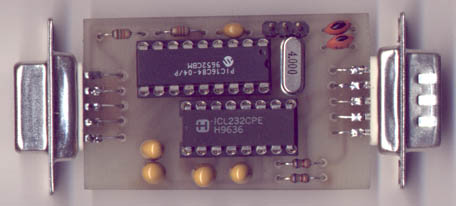
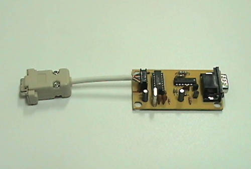
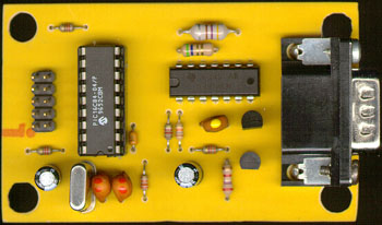
Anyway, here it is ;-). (Photo was taken using a flatbed scanner.)
A lot of people helped me during the development (some of them not knowing they actually did :-) ). First of all, most Commodore material was obtained from the Funet CBM archive. A warm personal thank goes to the following people (in no particular order): Frank Kontros (1351 user's manual, 1351 patents and testing a real 1351 mouse, providing me with lots of interesting data); Endre Turóczi (help in manufacturing the boards); László Oravecz (1351 mouse data). Thanks go to others whose products I used: Tomi Engdahl (lots of PC mouse information), Jens Dyekjær Madsen (simple PIC programmer), Silicon Software Studio (PIP02, PIC programmer software), Microchip Technology Inc. (MPASM, not mentioning the wonderful PIC series ;-) ), Holophase Inc. (Circad). The document was edited in Netscape Composer, pictures were customized in Adobe Photoshop 4.01 (Win95).
This is version 1.01 of this document (2001.01.08), with notes on substituting
the PIC16C84 chip with a '16F84, and fixing a bad link.
From the other hand, a mouse would be handy in a lot of situations. Lots of programs would suggest mouse besides, or rather in favour of the joystick. (Try drawing something in Art Studio using a joystick and a mouse; you'll know what I mean. The feeling you get is slightly different.)
Speaking of the present, Commodore mice are at least here (Hungary, Europe) unable to purchase. Unfortunately, neither I have an original 1351 mouse (though I've been trying hard to obtain one) :-(. As far as I know, they're still available in the US. But that's not a real difference anyway; from my point of view, they're hard to purchase, and they're expensive. You may or may not agree with me - would suppose depending on your local possibilities.
But one can purchase a perfect, good-looking and cheap mouse for PC compatibles simply anywhere over the World. Why not trying to convince these mice to work with the C64, if possible?...
This last 'if' is, BTW, quite more complicated to prove that one would expect at the first look. ...The Commodore 1350/1351 and the PC serial mice have the very same plugs ;-), and quite the same mechanical and electrical design. But unfortunately, these are also their very last similarities. The main problem in interfacing a serial mouse to a Commodore is the different communication method (and also some voltage level incompatibility problems). In short, Commodore mice follow Commodore traditions. ...Or rather, conditions. For obvious reasons, Commodore had to produce a mouse that can be connected to the joystick port of their most widely spread computer, the C64. And speaking of the other side, the PC serial mice, their features also come from history. Neither IBM has planned supporting mice when releasing the PC; when mice became important, the PC / mouse manufacturers also had to do some work-around to present real mouse support. Besides the quite more expensive solution (bus mouse, with a dedicated ISA interface card), the cheapest way was to hook the mouse to an existing (most likely unused) RS-232 serial port, draw power for the mice electronics from some less important RS-232 port pins and let the mouse transmit movement data by serial (RS-232 standard) communication. Later IBM introduced PS/2 mice, with a dedicated mouse interface and port on the new IBM PS/2, but this design haven't become widely supported for a long time. Serial mice are still very common in the market.
As it seems from this short overview, interfacing a PC mouse to a Commodore computer is rather complicated. The interfacing either implies hacking into the serial mouse (or whatever kind of mouse), with a little hope that the inner components, diodes, sensors don't get fried, + one also needs the appropriate (probably programmable) logic substituting the custom chip of the C= mouse.
Or it implies a mouse to be wired directly to the computer - with the drawback of patching every single involved code, to make your favourite applications handle your particular (on the C= : nonstandard) mouse type. However, I've seen this done so far; Frank Kontros interfaced Amiga mice to the C64 using few TTL glue logic, and some programs even handle the Amiga mouse (without any extra hardware) on the joystick port very well (one example is the Fart Studio, a slightly modified version of Art Studio 2.3). Another example is wiring a serial mouse directly to the C64 (with also no extra hw, just powering the serial mouse from TTL supply levels by connecting it to the expansion port - some mice are so simply designed that they're happy with even as low input voltage swing as 0 - +5V is). This latter was done by Soci / Singular crew (he supported this solution in Fuckpaint, his interlace mode graphics editor). Either solution is possible. Additional problem of the Amiga mouse (besides the availability) is: polling the joystick pins involves lots of processing power, so it's possible to support it in a program like that (graphic editor), but probably won't be good in other programs where processing power is an issue.
Or we could talk about a different approach: to create an interface board, with no fiddling in the PC mouse and / or the programs at all but rather emulating Commodore's own mice by this board somehow. This seems to be most difficult to make, but also seem to imply the less problems after the interface is present (no problems with mice inside, and also no problems with applications that support at least joysticks).
The interface described in this article is based on a Microchip PIC16c84 microcontroller, which is a small, rather cheap 18 pin chip containing a small CPU core, 1Kx14 bit EEPROM program memory and a lot of other useful things. You just have to plug the interface to the joystick port, plug a PC serial mouse (supporting either Microsoft or Mouse Systems protocol) to the interface socket and voilà...
The simplest mouse works just this way - it has no more electronics inside, the optosensor and button signals simply go directly to the host computer (only some electrical interfacing, level comparing takes place). The two typical representatives are the Commodore Amiga and the PC bus mice. The drawback is that then it's the host computers responsibility to decode the movement from the optosensor signals, which either takes a lot of processing power (involves lots of polling) or a more friendly (=complex), dedicated mouse interface circuitry.
Most mouse designs, including the C=1351 and most PC mice work another
way. There is a small 'intelligent' custom chip, 'controller' inside the
mouse, tracking the optosensors signals, the movements and sending the
movement data together with the buttons states to the host computer in
encoded data format. This method has the advantage of providing simpler
/ more efficient driver software on the host computer (not mentioning history,
like the background of serial and C= 1351 mice). As I mentioned, all RS-232
type serial, PS/2, USB mice and the 1350/1351 belongs to this group.
The 1351 has two different operating modes. You can use it in joystick mode (that is, when you move the mouse, it will act as you moved a joystick). This is also called 1350 or compatible mode. To joystick mode, one must hold the right mouse button pressed while powering the system up. Inside, the mouse logics transform the mouse movements to joystick events by a simple method: whenever you move the mouse, the chip shorts the joystick direction line of the appropriate direction to ground for a period of ~20 msec. (Miscellaneous info: the left mouse button is wired as if it were the fire button, while the right button is mapped to the POTX line). If you move the mouse slowly, the effect represents the real movement quite well, but the relation is broken as soon as the mouse movement is continuous (fast). Still, this mode is very useful in case a particular application supports no 1351 mouse natively.
In true 1351 (proportional) mode, the mouse can track and transmit the real movements to the computer. If you see the C64 joystick port, you probably suspect that Commodore engineers should have lived hard days when they had to invent a protocol like this ;-). BTW it also costed me a lot of time until I fully understood its inners. Until the point that probably all Commodore mouse supporters know, the proportional movement is transmitted via the SID POTX and POTY lines.
On the C64 side, tracking the mouse position goes the following way:
* if Prev_pos is large AND Current_pos is large (>xx)
AND
* if signs are opposite
Then toggle sign. No fuss right?"
The whole digitizing process is done by the SID chip itselves. The process takes 512 clock cycles. In the first 256 cycles, the SID pulls the POTX/Y outputs active low, discharging the capacitors completely. After this period, it turns this pull-down off from the output, starts counting the cycles (one increase per clock cycle) and starts monitoring the line. The capacitor starts charging (by the current flown from +5V through the potmeter). As soon as the voltage on the capacitor exceeds the SID input level threshold, the SID captures the counter value and puts it into the SID POTX/Y register. The process repeats again and again.
(Note: if the resistance is too low, the capacitor charges up 'immediately',
so the value captured by the SID is '0'. Similarly, if it is 'too high'
or 'infinite', the capacitor won't charge up during the measuring period,
so the SID will capture '255'.)
The 1351 inners were finally discovered by reading the original 1351
mouse patent document (US No. 4,886,941, 1989.12.12). Here is a shorted
description of the algorithm presented by the MOS 5717 custom chip in the
1351 mouse.
| Pin number | Signal name | Task |
|---|---|---|
| 1 | UP | Up dir. input |
| 2 | DOWN | Down dir. input |
| 3 | LEFT | Left dir. input |
| 4 | RIGHT | Right dir. input |
| 5 | POTY | Paddle Y dir. input |
| 6 | FIRE | Fire input |
| 7 | +5V | Supply voltage output |
| 8 | GND | Common ground |
| 9 | POTX | Paddle X dir. input |
In this document, I'll avoid going deeper into PS/2 or USB mice, since I found that at least PS/2 mice would need another method of programming (their bitrate is quite high, at least for this particular interfacing hardware) and will concentrate on serial mice.
Here is a table, with the usual setup of connecting a serial mouse to the RS-232 port. This table refers to the pin numbers of the smaller, Canon DB-9 connector of the RS-232 standard. Also, the signal names are from the point of the PC, not the mouse itselves.
| Pin number | Signal name | ...on the mouse |
|---|---|---|
| 1 | DCD | Not Connected |
| 2 | RxD | Serial data |
| 3 | TxD | -Us |
| 4 | DTR | +Us |
| 5 | SGND | Common ground |
| 6 | DSR | Not Connected |
| 7 | RTS | +Us |
| 8 | CTS | Raised to +Us |
| 9 | RI | Not Connected |
The connections were discovered by experience, and few schematics of different mice. Thus, it's more likely not all mice need all lines to be connected; some mice should use only one of +Us lines. However, since this layout seems to fit for all mice, I kept this table in mind when designing the circuit.
Serial mice communicate by standard RS-232 data packets. The communication is usually unidirectional, only the mouse can send data to the computer. No other lines are used in the process, they're rather used as power supply for the mouse; only RxD, the received data line is involved. The control lines are not only used as power supply but they also deliver the positive and negative signal voltages for the RS-232 communication. Most mice communicate at 1200 baud by default (most of them are 1200 baud only, and a very few can be switched to higher baud rates). The actual data format varies type to type. In general, most mice except Microsoft and its variants use 8 bit datas with one start and two stop bits and no parity (say, 8N2 configuration). Microsoft variants use 7 bit data packets with the same other parameters. Also, most serial mice have three mouse buttons, except Microsoft compatible ones having only two. (Exception: some newer Microsoft variants, like the Logitech MouseMan and compatibles (like most Genius mice) have also three buttons).
(I avoided discovering newer mice with wheels and such gadgets, but they should just be slightly enhanced variants of the above).
Since a lot of mice are compatible with just two main mouse protocols, I'll concentrate on these and omit discussing others. These are the Microsoft and the Mouse Systems protocols. If you purchase a mouse in a shop, you'll most probably find either or both of these (today, probably Microsoft variants), and no other kind of serial mice at all. Older mice also tend to support these protocols, with the exception of the oldest ones. Finally, if you have an incompatible mouse, you can still check my interface controller source and modify it to support your particular mouse type.
Here is the summarized description of the data format of these mice.
| Bit # | ||||||||
|---|---|---|---|---|---|---|---|---|
| 6 | 5 | 4 | 3 | 2 | 1 | 0 | ||
| Byte # | 1 | 1 | Left | Right | Y7 | Y6 | X7 | X6 |
| 2 | 0 | X5 | X4 | X3 | X2 | X1 | X0 | |
| 3 | 0 | Y5 | Y4 | Y3 | Y2 | Y1 | Y0 | |
The packet contains three 'bytes' (rather: 7 bit datas). Only the first chunks bit6 is one, all others are 0 (this is for syncing; the receiver side has to know whether a byte is the first or another byte of a packet). X0...X7 is the 8-bit signed data of the movement in the X direction since the last sent data packet (say, Dx). So is Y0...Y7 to the Y direction. Left and Right are the mouse button bits. The mouse sends a 1 bit in these places when at least one of the buttons is pressed. Whenever anything is changed in either the position or the buttons state of the mouse since last transmitting time, a data packet is generated and sent.
As an addition to the above protocol, Logitech MouseMan mice support the same but with a rather weird extension. These mice have three buttons. When the third button is pressed, the mouse sends a non-standard packet of 4 bytes. The 4th byte can be identified by its 0 on bit6 position (instead of 1, as the first byte would be). If it's present, bit5 of this byte corresponds to the state of the middle button. (This info was taken from the documentation of GPM, the General Purpose Mouse server for Linux; I also fiddled a bit with Nosey, which is a mouse detector written for Linux. Thanks a lot for the authors...).
| Bit # | |||||||||
|---|---|---|---|---|---|---|---|---|---|
| 7 | 6 | 5 | 4 | 3 | 2 | 1 | 0 | ||
| Byte # | 1 | 1 | 0 | 0 | 0 | 0 | Left | Middle | Right |
| 2 | X7 | X6 | X5 | X4 | X3 | X2 | X1 | X0 | |
| 3 | Y7 | Y6 | Y5 | Y4 | Y3 | Y2 | Y1 | Y0 | |
| 4 | X7 | X6 | X5 | X4 | X3 | X2 | X1 | X0 | |
| 5 | Y7 | Y6 | Y5 | Y4 | Y3 | Y2 | Y1 | Y0 | |
This mouse transmits 5 byte long packets of 8 bits each. The first byte also acts as syncing. Bit0 - bit2 correspond to the three mouse buttons. In opposition to Microsoft mice, these bits give 0 when the buttons were pressed, else they're 1. X0-X7 and Y0-Y7 are the same as described above. The 4th and 5th bytes should contain movement data while transmitting the first three bytes.
I think that's all regarding serial mice. They're not so much dirty
as the 1351 design is, so writing a mouse handler for them should be much
more friendly than writing a 100% handler for the 1351 (an 1351 handler
would be hard to code even more, if the used hw had no counter type digitizer).
>From the other hand, since transmitting a data packet takes noticeable
time (more than an 50hz frame), the mouse pointer doesn't move as smooth
as seen on the Amiga, for example. PS/2 or USB mice should be better in
this subject.
The heart of this interface is a microcontroller (Microchip PIC16C84, but some others in this series would also fit - 16F84, 16CR84, even a 16C61). It is a small programmable (and easily reprogrammable) EEPROM based chip, with the following capabilities:
The other main part of the hardware is a MAX232 RS-232 interface chip. It is becoming popular; in short, this chip provides both the required levels (about +-10V) from a single +5V supply (using only 4 electrolytic capacitors) and RS-232 level conversion. It appears that this is the easiest way, even for such simple circuit as this interface is, to provide supply voltage to the mouse. I've been trying hard to find a smaller/simpler/cheaper way of presenting the needed voltage swing @ 15-20 mA for the mouse, but it turned out to be wasting too much time for almost nothing. Today, one can purchase a MAX232 or its equivalent with no trouble at all, and the chip is also becoming quite cheap.
As you see the schematics, almost everything is straightforward and follow the manufacturers recommendations. The microcontroller (U1) derives its clock from Y1; C1 and C2 are recommended by Microchip for such clock/crystal value. Pin4 is tied to VCC, to activate the built-in power on reset circuitry of the microcontroller.
Port A is used for inputs. In fact, only two pins are used: RA0 is the serial input pin, coming from the serial port through the MAX232 chip. RA2 comes from J1, and it is used as configuration input: if it's tied to GND, the interface boots up in joystick emulation mode, else in proportional mode. (One could probably replace it by a DIP switch or a small push button (this latter with modifying the init code in the microcontroller)).
Port B is occupied by the outputs (five joystick lines that go directly to the port, and the POTX/Y lines that are connected through resistors). PortB.0/INT is connected to POTX. It is used for the same purpose as Sync in the original 1351 mouse: with it, the microcontroller receives an interrupt request whenever this input drops.
The resistors on the POTX/POTY lines play exactly the same role as the
resistors in the original 1351: they limit current when the two sides pull
the lines to the opposite levels. The reason of using 11k resistors is:
as I found out, the outputs of the PIC microcontroller have much less self
resistance than the 5717 had (while the 5717 was manufactured in some kind
of NMOS technology, the PIC is a true CMOS chip with as much as 20mA sourcing
capability per output). This value is experimental, it causes about the
same effect on the values received in the POT registers as the 5.1k in
the original hardware (100% compatibility :-) ).
The configuration of the MAX232 is also quite standard. Almost nothing
but its voltage step-up / invert capability is used, plus one of its RS-232
--> TTL receivers. The positive and the negative output voltages are buffered
by C7 and C8, then supplied to the serial mouse.
Including R3 and R4 are also a result of some headache and cursing :-/.
It took some time to realise, that these serial mice in fact quite depend
on the electronics side of the RS-232 standard. Inside, most of them are
powered from a lower (sometimes 5V) supply voltage, that is regulated from
one of the inputs. The voltage drop is usually achieved using a Zener-diode.
Since the unit is powered from the serial port, and since the real RS-232
port lines have a pretty standard, 'high' series resistance, the mice themselves
have no series resistors; the voltage drop appears as a result of current
flown through the self-resistance of the RS-232 port and the Zener-diode
to GND. If I used no series resistor, it would cause something (the Zener-diode)
to burn inside the mouse, if the power supply was 'strong'. The MAX-232
would act different: probably no step-up and inverting took place because
the first output (the doubled one) would disappear from C7 in a short minute,
causing the mouse not to work as a final result.
The software can be divided into subparts as the initialization, the main loop, the IRQ service routine and subroutines. The init is rather common, featuring
Because of the nature of this method, there are two critical parameters.
The first one is the timebase, the time delay of one movement unit. The
value is experimental, in the program it's 60 times the IRQ handler time
period, about 3.84 msec (in other words, ~5.2 units of movement corresponds
to the 'original' 20 msec delay of the 1351 mouse). Another important value
is the maximum allowed displacement (the maximum time the mouse tracks
a finished fast + long movement). In the code, this is done by the Clclimit
routine, that limits additions to the current coordinates to +-64 (also,
an experimental value) thus no additions can result in X or Y values outside
the +-64 interval.
Reading mouse data (Serin), interpreting the bytes, updating the X
and Y pointers (by calling Clclimit first, then adding the limited deltas
to X and Y) are done in the respective main loops. The reason of not using
one 'parametric' main loop was speed and avoiding lots of gotos (it was
simpler this way); the mouse packets of the Microsoft and Mouse Systems
mice differ a lot from each other, so they need different process. The
mouse buttons are also interpreted here, by setting the respective bits
of the OUTBUF variable. The real update of the joystick line states is
done in the IRQ routine.
Similarly to the 1351, the left mouse button is mapped to FIRE, and
the right button to POTX (whenever the right button is pressed, one gets
<$80 values in the POTX register). Since both Mouse Systems and Logitech
Mouseman mice have a third button, I took the opportunity to map it to
POTY, similarly as above.
There are still two components to describe: the IRQ routine and the
serial receiver routine (SERIN).
This microcontroller has unfortunately not much useful gadgets to play with :-(. Neither does it have a hardware RS-232 port, so RS-232 communication must be handled by software. This routine polls the serial input line for startbit and reads either 7 or 8-bit data according to wflags.mouse_t (assumes 7-bit data if Microsoft mouse is on the port, else 8). The timing is derived from TMR0 (the only timer of the microcontroller). If the timer IRQ routine is active, Serin relies on its update of the Sch variable. Sch is increased every 64 instruction clocks. For the needed bit-time of 1200 baud, this IRQ period must be counted again 13 times (resulting in the period of about 1202 hz, close enough to 1200). As soon as a startbit is sensed, Serin keeps on waiting for Sch increasing by 4 (making sure that it's somewhere inside the first third of the startbit time). After this, Sch is decreased by 4 and one bit is shifted to the register addressed by FSR every time Sch exceeds 13 (then it's always decreased by 13). At the end, if 7-bit data is set the value is shifted to the right once more. Finally, it returns as soon as stopbit was sensed.
Finally, some words on the IRQ handling. In short, the PIC series has a 'full featured' IRQ handler with a lot of possible IRQ sources. The IRQ routine must start at address 04. No priority is set, the same interrupt service routine is activated as soon as an IRQ occurs. The return address is put onto the stack, but neither the status word, nor the working register is saved by hardware :-O. The routine is also responsible to clear the IRQ flags, except the global interrupt enable that is taken care by the RETFIE instrucion. At the end, the regs must be restored.
Because of the several different tasks the interface must be able to do, I changed this one a bit, at least in the subject of the hardwired start address of the IRQ handler. My code here saves the registers, then reads the 'irql' variable and writes it to PCL (program counter low), executing a 'computed goto'. The next instruction fetch is done from the address pointed by PCL. I didn't care about PCH, so all IRQ routines must start below $0100, but it was enough (and definitely faster).
There is another quirk. TMR0 is the only useable counter in the 16c84, and it's only 8-bit and non-autoreload :-(. For a constant timing, one must always reload it 'by hand' in the IRQ routine. Commodore relative people could be suspicious about this, since the IRQ could be accepted with non predictable delays. However, fortunately, the simple architecture of the PIC helps: all instructions are executed in a single cycle. Even jumps, that effectively occupy two cycles are executed as two separate instructions :-) (the GOTO itselves, and a NOP, flushing the read instruction from the instruction pipeline). Whenever an IRQ occurs, it can take into account as soon as the current instruction finished. In other words, all IRQs are 'cycle exact', without additional fiddlings around the timer. So finally, reloading the timer in the IRQ service can provide constant time period, since the reload happens in a predictable minute.
The joystick emulation interrupt routine itselves is quite simple. After saving the regs and setting TMR0, it increases Sch (serial timing), decreases Stickcnt and checks if it's 0. If so, updates the X position like above, and reloads Stickcnt. If it's 30, updates Y pos. Finally, writes the appearing value in Outbuf to TRISB (the data direction register of PORT B).
Similarly to the joystick mode, the microcontroller must read the mouse data from the mouse and update its inner variables accordingly. Since real proportional movement is transmitted, there is no need for limiting as in joystick mode.
What is exclusively needed by 1351 emulation?
A new problem comes in: with the need of a cycle exact external IRQ, all other interrupts must be disabled (else, a currently served IRQ would cause delay). Thus, TMR0 interrupts must be disabled. But then the timing of the serial input routine must be handled different, since it depends on the TMR0 interrupt and its task of incrementing Sch with each run. This was fixed in Serin; when TMR0 IRQ is disabled, it itselves polls the timer and updates Sch accordingly, using Scl, another variable that is increased by 4 times the cycles spent since last update. Carry from Scl to Sch is calculated, and makes the calculation (more) precise.
Second, right after the external interrupt routine starts, the process needs TMR0 for its own timing. One 'full' SID measuring cycle can't be served in one long delay, since it would last longer than half a bit-time of a 1200-baud bit, so the program would lose some incoming bits occassionally. All subsequent timings are done using TMR0; INT is disabled. ...This would, in the first place, screw up the own timer-update of Serin, since TMR0 gets changed without notice. (Both Serin and the pulse timing needs TMR0 at the same time, since it is the only timer in the 16c84). Finally, it was fixed using two semaphores, wflags.TRACE1 and wflags.TRACE2. Both are 0 by default. As soon as the pulse interrupt was executed, it sets TRACE2 high, and it's only cleared at the end of the whole pulse generation process - telling Serin not to touch the timing variables at all. While this period, Sch is updated in the TMR0 IRQ together with the other tasks. On the other side, the U_sercnt routine calculates the time since its last run, and checks for TRACE2. If it's not set, sets TRACE1 and updates Scl and Sch. At the end of the update, it clears TRACE1. The INT IRQ routine updates Scl and Sch itselves, if TRACE1 is 0 at the time of the interrupt request, else leaves them alone since they're currently taken care by the U_sercnt routine. (Phew...)
So, going back to the first (external) interrupt service of the process, TMR0 IRQ is enabled, serial counter is updated and so on, and the second IRQ service routine address is set (Pirq2). The timing is 128 cycles (from the point of the first IRQ).
Pirq2 simply updates Sch and sets the next IRQ handler (Pirq3). The timing is too, 128 cycles from the previous IRQ. First (256) cycles, e.g. discharging period of the SID is spent until executing Pirq3. The reason of not spending it in one, is the better resolution of updating Sch (2 times 2 units, instead of 4 units once).
Pirq3 would set 64 cycles for the next IRQ, as the delay known from the 1351 inners, but it sets few to give time advantage to Pirq4.
The real tricky part (if the semaphores were not so much like that ;-) ) is found in Pirq4. This routine takes care of pulling POTX and POTY in a particular minute, independently from each other, so a given number of cycles are spent until raising them. I think I'll describe it in detail in one of the next paragraphs. At first the routine sets 128 cycles (+ a few) to TMR0, to keep track on time whatever the inner routine does. At the end, it polls the timer to know the end of this period - then simply disables TMR0 IRQ, enables INT, updates Sch, sets Pirq1, turns both POT outputs inactive and returns from the IRQ service. One cycle was served, it starts again from the start. Since TMR0 was set, U_sercnt (if runs) can use it to count any additional cycles and add these delays to Scl/Sch.
The cycle generation. ...Well, after all, it's not _so complicated _after I implemented it and think it over again ;-). This is a parametric delay line. It is optimized to be able to write to TRISB whatever minute between the barriers of the 0..126 cycles period. Pulling POTX and / or POTY is done by a simple write to TRISB (_what to write, is determined by an external routine, with comparing the X and Y values to each other; it's either setting POTX, POTY or both to active state). The time delays are done using GOTO *+1 instructions, that act effectively as "2 cycle NOP"s.
A delay cycle looks something like this in general:
Still, there is one problem. The writes and the jumps also occupy some cycles. There are special cases, when either stage is not needed (parameter is 0, so first delay program must be skipped entirely, or the two coords are the same, so the pulling must be done in exactly the same minute). Another special case when they're needed, but they're so short that the above algorithm could not provide them because of the time of the jumps / other additional instructions.
The final solution is a bunch of code sequences that do some special time delay and write to TRISB, then read a value and write it to PCL, executing a 'computed GOTO'. All small pieces read a 'program', a sequence of bytes by indirect addressing, always increasing the pointer to the next byte. The read byte is either loaded to PCL or TRISB, depending on the current routine.
The whole bunch is organized and chained by an external routine, 'Clcline', that is executed once whenever both the X and Y coordinates are known. The input parameters that the routine uses for operation is the relation of the numbers (more/less/equal), the value of the smaller one, and the difference between the numbers. From the relation, the TRISB masks are deducted (current value of Outbuf, + the POTX/POTY mask; the second writing of course always pulls both, and the special case of equality is also needs pulling both at once). If Y is lower, the values and the masks are simply swapped. Next decision depends on the smaller value, and the last on the difference. The routine checks for _all special cases, decides which address (= which code piece) to use, sets the addresses / TRISB values to the next position of the delay program accordingly. The delay values are calculated with keeping in mind all additional time delays in the pieces. Finally, the program lets the IRQ routine know the start address of the new program: it writes this to the 'Line' variable, that is read by the IRQ code.
The delay program occupies 6 bytes in the worst case. Line1 and Line2
are reserved in the RAM of the microcontroller. Of course, the routine
uses double buffering: it never tries to change the currently active delay
program.
Phew... I think it was easier to explain than do it. Analysing all
special cases was a pain in the *ss. Still, despite the lot of decisions
the calculation routine must do, fortunately, it runs pretty fast. ...Check
the mentioned code if you want to see something beautiful ;-).
BTW, the other tasks are pretty easy. Reading the buttons goes the similar
manner as described in joystick mode. There is one difference: similarly
to the 1351, the right button is then mapped to UP, and as expected, middle
button is mapped to DOWN in this case. ...However, there is again a quirk
with the buttons: their state on the output port is only updated in the
IRQ handler, so they're only actualized if an IRQ was executed from the
SID chip. This is not a real drawback, as I think, since it won't make
sense to disable the SID POT lines on the C64 completely and read the buttons
only. As far as the mouse position is read on the C64, the buttons are
updated correctly.
You'll also need these components:
| Component | Quantity | Note |
|---|---|---|
| PIC16C84-04/P | 1 | See note |
| MAX232CPE |
|
Clones will fit too |
| 4Mhz crystal |
|
|
| 10µF electrolytic capacitor |
|
16V, tantalum |
| 15pF ceramic capacitor |
|
|
| 100nF ceramic capacitor |
|
|
| 11k resistor |
|
1/8W, 5% |
| 680 ohm resistor |
|
1/8W, 5% |
| DB9 plug, male |
|
|
| DB9 plug, female |
|
Both simple plugs |
| DIP 20 socket |
|
|
| DIP 18 socket |
|
|
| Pin header |
|
Just a small piece for J1 |
| A jumper cap |
|
J1 |
All components should be available at local resellers. The PIC16C84 costs here about HUF 2000 ($7-8 if I'm right).
You can substitute the 16C84 by another (cheaper?) PIC micro, like a 16F84, 16LF84 or even a 16C61, but keep in mind that they need different programming hardware / software (but they're code compatible). PIC experts would probably take the latter, or a more frequently used 16C71, since it's a (maybe cheaper) OTP chip. Not tested. Should make sense to first-try with a PIC16C61-04/JW before blowing the code into an OTP version chip.
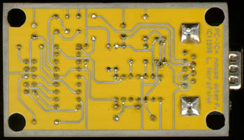
First you must reproduce the board. I let this up to your favourite method; you can find here the process that I made mine. There should also be companies manufacturing boards in small quantities. Anyway, here is the PCB (300 dpi). You can use both plastic and fibre-glass based boards - the latters are mechanically stronger, but are also harder to cut/drill. If you're bored of making boards, you can probably skip this one and wire the components together without using a board at all - the circuit is quite simple, just be sure to use IC sockets and avoid shorting wires together.
Check the board against breaks, gaps on the traces and shorts. A short can make the interface fail to work, or even blow the fuse / something else inside the computer. Also take care of the simple fact that the border around the circuit is only intended to show the physical size of the board when you cut it - this copper field must entirely be removed when cutting, since it is anyway not part of the circuit itselves and it would cause all connector pins to short.
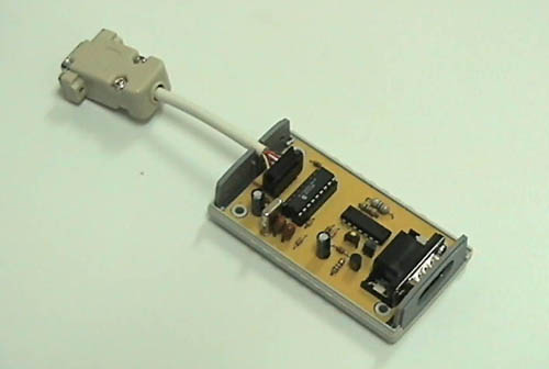
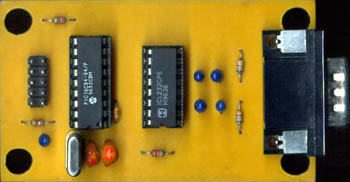
Start inserting the components in the order of height. Resistors, the crystal, IC sockets, capacitors, finally the jumper and the DB9 plugs. Use a termostate soldering iron. The unipolar components are marked - their positive side go to the rectangular pads on the board. Pin1 of the chips are also marked. Finally, the board must be surrounded by the pins of the DB9 connectors. Use small pieces of wire to connect the top DB9 pins to the board. Because the bottom side of the connectors are soldered to the board, and the top is also fixed to the holes by those wires, the construct is quite stable mechanically.
This figure will probably help (you can also check the title photo):
When everything is done, you can also put the MAX232 into its socket.
Before you could finish the work, you must burn (in PIC dialect: blow) the program into the PIC. ...This task needs some preparation. If you don't have, you must obtain a PIC programmer software / circuit. There are a lot around the Net; I personally used PIP02 by Silicon Software Studio, and as programmer hardware I quickmade one of the simpler programmer boards from Jens Dyekjær Madsen. I've seen PIC programmer applications even for Linux. You can obtain such stuff from the Net by taking the above links or by submitting a search with simple keywords on this subject.
For a simple reproduction, here is the compiled code in Intel HEX format (probably all programmer stuffs can load it). Else, you can take the ASM code and recompile it with MPASM.
A quick note: if the programmer software handles configuration bits wrong, the chip must be set to XT oscillator, WDT on, PWRT on, CODE PROTECT off.
When you programmed the PIC, it's ready to be seated into the socket.
Here is the moment you've been waiting for: try if the circuit works. Set the jumper to joystick mode. Plug the interface to the joystick port of a C64. Plug a serial mouse to the interface connector. Carefully, switch the system on (it probably makes sense to turn the display on first). If you notice no effect (no random keypresses), O.K. Load one of your favourite joystick-controlled programs (mine was the desktop of Final Cartride III). Move the mouse. The pointer must follow the movement...
If this was successful, switch it off, change to 1351 mode by the jumper, and turn the computer on again. Load, for example, one of the simple example programs from the 1351 demodisk (don't forget to kill your FC III. before you run them - it screws up custom IRQ handlers if the program gets back to Basic). Move the mouse as above... Hope it works good.
If it doesn't seem to work, first check the microcontroller if it really
has the program loaded (put it back to the programmer socket and try to
read out its contents). Check polarity of the capacitors (...well, if one
of them has just exploded then it's bad luck but at least you know the
problem...). Traces, again. ...Have I told you to put the chips into sockets???
Since the circuit is simple, you can't really do much mistakes, the interface
is quite well supposed to run at the first try.
This interface design uses the chip's external interrupt capability. Unfortunately, the POTX signal that was enough for the 16C84 to sense an interrupt request, is too off for this Schmitt-trigger input :-(. What you see from this, that you can use the 16F84 as a 16C84 substitute - but the interface won't work in native 1351 mode at all! The same applies, BTW, for the 16CR84 chip.
Fortunately, there's a trick that you can do to get the interface to work. It just needs one unused transmitter and one receiver gate of the MAX232 chip for conditioning the POTX signal to meet the requirements ;-).
First of all, you can probably do better and implement that emulation mode selection using the mouse itselves. Then J1 could be left from the board.
Another thought is to adapt this design to other mouse standards: PS/2 and USB mice in particular. A lot of arguments would be beside them. First, serial mice will slowly becoming disappeared - in favour of those above. The second, they work from TTL levels, so no special care around the power supply is needed - these mice can be powered directly from a +5v supply, making the hardware simpler.
On the other side, implementing support for them seems to be hard. I don't know USB mice, but PS/2 mice transmit data quite fast. The communication is serial synchronous, with a clk and a data line. Data bits are clocked by the mouse - about 30-60 µsec each :-(. This is definitely too fast for this hardware, at least for 1351 emulation. Here, IRQ is hooked by the SID POT pulse generation - and with polling, the IRQ must never delay the execution for more than 15-20 µsec. I can state that this is simply impossible to accomplish. ...Maybe, with a more sophisticated microcontroller? It would be possible to move the whole design to an Atmel AVR chip (for example, an AT90S2313) - but all code should then be rewritten, including problematic (1351 timing) code pieces.
Also, it would be possible to support Amiga mice. However, as I see they're becoming extinct 8-) as much as the original 1351 :-(. It would also be possible to support the Amiga mouse protocol on the Commodore side (besides the joystick and the 1351 mode) ;-).
On the other hand, it could also be possible to support other host platforms. Currently, similarly to the 1351, the interface should work with C64 and C128.
It doesn't work with a Plus/4, not even in joystick mode if you connect it through a simple wire-to-wire C64 joystick interface cable. It works in joystick mode (tested...), if you have a similar joystick interface for the beast as I do - check my ultimate Plus/4 joystick interface document if you're interested. Well, not to forget it: you can also use the interface on the Plus/4, even in native 1351 mode if you have a SID card from Synergy - its joystick port is perfect, and it also includes the POTX/Y lines; see your SID card manual for more details.
I've also tested it on a PAL VIC-20. It works well in joystick mode (you should have seen me playing Star Battle with the mouse, kicking some butts ;-) ). Even the right and the middle buttons are readable through the POT registers of the VIC-I. It won't work in 1351 mode, however. Even if the computer handles the paddle inputs in a similar manner (does it?!), its clock would be way too high to the current emulation code - and probably also for a real 1351.)
Supporting other host systems, again, should be an easy problem to solve, since the interface is 'intelligent'. You can implement whatever algorithm in the PIC. With this advantage, supporting another host (at least in joystick mode) is just a matter of hardware interfacing (meet the requirement of the port characteristic on the host system, and draw power from somewhere) and some easy code-reorganizing inside the PIC.
First, the original prototype I created in February 1998. Unfortunately,
I have no photos. Can you find, where the PIC16c84 is? ;-)
 |
 |
Revision C, still somewhere around 1998. MAX232 power (there
were another 2 versions powered from either a MAX680 or a TL497)
 |
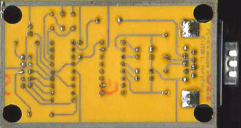 |
The straight predecessor of the described circuit is Rev D. Note the minimized component number and the small board :-). Almost everything was left from this one, even the RS-232 power supply since some mouse still work from TTL levels. Had a fault on the board, the mouse received the supply voltage with bad polarity :-O. Unfortunately, I have no photos.